Primero, debe conectar la pantalla al controlador. Conectamos de acuerdo con el esquema:
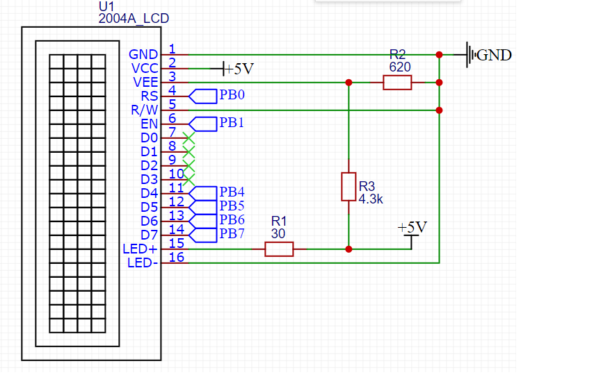
PB0 - PB7 - salidas del controlador.
Asignación de pines de pantalla:
| Número de PIN | Señal | Asignación de señales |
| 1 | GND | Tierra (cable común) |
| 2 | VCC | Energía + 5V |
| 3 | VEE | . . 10-20 , . |
| 4 | RS | : 0 – ; 1 – . |
| 5 | R/W | :
0 – ; 1 – . , . |
| 6 | EN | . , «» . |
| 7 | DB0 | . . |
| 8 | DB1 | |
| 9 | DB2 | |
| 10 | DB3 | |
| 11 | DB4 | . |
| 12 | DB5 | |
| 13 | DB6 | |
| 14 | DB7 | |
| 15 | A | (+) |
| 16 | K | (-). . |
Entonces, la pantalla está conectada. Es hora de enseñarle al microcontrolador a trabajar con él. Decidí crear mi propia biblioteca para poder usarla en diferentes proyectos. Consta de dos archivos: lcd_20x4.hy lcd_20x4.c
Comencemos con el archivo de encabezado.
#ifndef LCD_LCD_20X4_2004A_LCD_20X4_H_
#define LCD_LCD_20X4_2004A_LCD_20X4_H_

#include "stm32f1xx.h"
#include "delay.h"
Al principio, incluimos el archivo de biblioteca CMSIS stm32f1xx.h ya que tengo una piedra STM32F103C8T6. La siguiente activación incluimos el archivo delay.h: esta es mi biblioteca para trabajar con retrasos basados en el temporizador del sistema. No lo describiré aquí, aquí está su código:
Archivo Delay.h
#ifndef DELAY_DELAY_H_
#define DELAY_DELAY_H_

#include "stm32f1xx.h"

#define F_CPU 72000000UL
#define US F_CPU/1000000
#define MS F_CPU/1000
#define SYSTICK_MAX_VALUE 16777215
#define US_MAX_VALUE SYSTICK_MAX_VALUE/(US)
#define MS_MAX_VALUE SYSTICK_MAX_VALUE/(MS)


void delay_us(uint32_t us); //  233
void delay_ms(uint32_t ms); //  233
void delay_s(uint32_t s);

#endif /* DELAY_DELAY_H_ */
Archivo Delay.c
#include "delay.h"


/*      */

void delay_us(uint32_t us){ //  233 016

	if (us > US_MAX_VALUE || us == 0)
		return;

	SysTick->CTRL &= ~SysTick_CTRL_TICKINT_Msk; //     0
	SysTick->CTRL |= SysTick_CTRL_CLKSOURCE_Msk; //
	SysTick->LOAD = (US * us-1); //
	SysTick->VAL = 0; //     SYST_CVR
	SysTick->CTRL |= SysTick_CTRL_ENABLE_Msk; //

	while(!(SysTick->CTRL & SysTick_CTRL_COUNTFLAG_Msk)); //    COUNFLAG   SYST_CSR

	SysTick->CTRL &= ~SysTick_CTRL_COUNTFLAG_Msk;	//   COUNTFLAG
	SysTick->CTRL &= ~SysTick_CTRL_ENABLE_Msk; //

}

void delay_ms(uint32_t ms){ //  233

	if(ms > MS_MAX_VALUE || ms ==0)
		return;

	SysTick->CTRL &= ~SysTick_CTRL_TICKINT_Msk;
	SysTick->CTRL |= SysTick_CTRL_CLKSOURCE_Msk;
	SysTick->LOAD = (MS * ms);
	SysTick->VAL = 0;
	SysTick->CTRL |= SysTick_CTRL_ENABLE_Msk;

	while(!(SysTick->CTRL & SysTick_CTRL_COUNTFLAG_Msk));

	SysTick->CTRL &= ~SysTick_CTRL_COUNTFLAG_Msk;
	SysTick->CTRL &= ~SysTick_CTRL_ENABLE_Msk;


}

void delay_s(uint32_t s){

	for(int i=0; i<s*5;i++) delay_ms(200);
}
La pantalla 2004A se basa en el controlador HITACHI HD44780. Por lo tanto, veamos la hoja de datos de este controlador. La Tabla 6 muestra el sistema de comandos, así como los tiempos de estos comandos.

Reescribamos los comandos necesarios en macros en el archivo de encabezado:
// display commands

#define CLEAR_DISPLAY 0x1
#define RETURN_HOME 0x2
#define ENTRY_MODE_SET 0x6 // mode cursor shift rihgt, display non shift
#define DISPLAY_ON 0xC // non cursor
#define DISPLAY_OFF 0x8
#define CURSOR_SHIFT_LEFT 0x10
#define CURSOR_SHIFT_RIGHT 0x14
#define DISPLAY_SHIFT_LEFT 0x18
#define DISPLAY_SHIFT_RIGHT 0x1C
#define DATA_BUS_4BIT_PAGE0 0x28
#define DATA_BUS_4BIT_PAGE1 0x2A
#define DATA_BUS_8BIT_PAGE0 0x38
#define SET_CGRAM_ADDRESS 0x40 // usage address |= SET_CGRAM_ADDRESS
#define SET_DDRAM_ADDRESS 0x80
Ahora necesita configurar los pines del controlador para que funcionen con la pantalla. Determine la posición de los bits en el puerto ODR del controlador. Preste atención a PIN_D4. Tengo el décimo bit registrado allí en lugar de 4. La cuarta salida no funciona en mi controlador. No sé con qué está conectado, pero en el registro ODR este bit es siempre uno, incluso antes del inicio de la inicialización del reloj del controlador. No sé con qué está conectado, tal vez la piedra no sea original.
//     ODR
#define PIN_RS 0x1
#define PIN_EN 0x2
#define PIN_D7 0x80
#define PIN_D6 0x40
#define PIN_D5 0x20
#define PIN_D4 0x400
A continuación, configuramos los registros de control para las salidas. Decidí hacerlo en forma de macros de preprocesador:
#define     LCD_PORT               	GPIOB
#define	LCD_ODR 				LCD_PORT->ODR

#define     LCD_PIN_RS()     		LCD_PORT->CRL &= ~GPIO_CRL_CNF0; \
							LCD_PORT->CRL |= GPIO_CRL_MODE0;    // PB0   -,  50

#define     LCD_PIN_EN()            LCD_PORT->CRL &= ~GPIO_CRL_CNF1;\
						 LCD_PORT->CRL |= GPIO_CRL_MODE1;        // PB1

#define     LCD_PIN_D7()            LCD_PORT->CRL &= ~GPIO_CRL_CNF7;\
						 LCD_PORT->CRL |= GPIO_CRL_MODE7;          // PB7

#define     LCD_PIN_D6()            LCD_PORT->CRL &= ~GPIO_CRL_CNF6;\
						 LCD_PORT->CRL |= GPIO_CRL_MODE6;       // PB6

#define     LCD_PIN_D5()            LCD_PORT->CRL &= ~GPIO_CRL_CNF5;\
						 LCD_PORT->CRL |= GPIO_CRL_MODE5;         // PB5

#define     LCD_PIN_D4()            LCD_PORT->CRH &= ~GPIO_CRH_CNF10;\
						 LCD_PORT->CRH |= GPIO_CRH_MODE10;         // PB10

#define     LCD_PIN_MASK   (PIN_RS | PIN_EN | PIN_D7 | PIN_D6 | PIN_D5 | PIN_D4) // 0b0000000011110011
Al final del archivo de encabezado, definimos las funciones para trabajar con la pantalla:
void portInit(void); //
void sendByte(char byte, int isData);
void lcdInit(void); //
void sendStr(char *str, int row ); //

#endif /* LCD_LCD_20X4_2004A_LCD_20X4_H_ */
Hemos terminado con el archivo de encabezado. Ahora escribamos la implementación de las funciones en el archivo lcd_20x4.c
El primer paso es configurar los pines para que funcionen con la pantalla. Esto se hace mediante la función void portInit (void):
void portInit(void){
//----------------------  ----------------------------------------------------

	if(LCD_PORT == GPIOB) RCC->APB2ENR |= RCC_APB2ENR_IOPBEN;
	else if (LCD_PORT == GPIOA) RCC->APB2ENR |= RCC_APB2ENR_IOPAEN;
	else return;

//---------------------    LCD-----------------------------------------------------

		LCD_PIN_RS();//
		LCD_PIN_EN();
		LCD_PIN_D7();
		LCD_PIN_D6();
		LCD_PIN_D5();
		LCD_PIN_D4();

		lcdInit(); //

	return ;
}
En cuanto a la función lcdInit (), esta es la función de inicialización de la pantalla. Escribámoslo también. Se basa en un diagrama de flujo de inicialización de una pantalla desde una hoja de datos:

//---------------------  -----------------------------------------------------------
void lcdInit(void){


			delay_ms(15); //

			sendByte(0x33, 0); //      0011
			delay_us(100);

			sendByte(0x32, 0); //      00110010
			delay_us(40);

			sendByte(DATA_BUS_4BIT_PAGE0, 0); //   4
			delay_us(40);
			sendByte(DISPLAY_OFF, 0); //
			delay_us(40);
			sendByte(CLEAR_DISPLAY, 0); //
			delay_ms(2);
			sendByte(ENTRY_MODE_SET, 0); //
			delay_us(40);
			sendByte(DISPLAY_ON, 0);//
			delay_us(40);


	return ;
}
La función de inicialización utiliza la función void sendByte (char byte, int isData). Escribamos su implementación. Se basa en un cronograma de una hoja de datos:

void sendByte(char byte, int isData){

	//
	LCD_ODR &= ~LCD_PIN_MASK;

	if(isData == 1) LCD_ODR |= PIN_RS; //    RS
		else LCD_ODR &= ~(PIN_RS);		   //   RS

	LCD_ODR |= PIN_EN; //   E

	//

	if(byte & 0x80) LCD_ODR |= PIN_D7;
	if(byte & 0x40) LCD_ODR |= PIN_D6;
	if(byte & 0x20) LCD_ODR |= PIN_D5;
	if(byte & 0x10) LCD_ODR |= PIN_D4;

	LCD_ODR &= ~PIN_EN; //

	LCD_ODR &= ~(LCD_PIN_MASK & ~PIN_RS);//     RS

     	LCD_ODR |= PIN_EN;//   E

	//
	if(byte & 0x8) LCD_ODR |= PIN_D7;
	if(byte & 0x4) LCD_ODR |= PIN_D6;
	if(byte & 0x2) LCD_ODR |= PIN_D5;
	if(byte & 0x1) LCD_ODR |= PIN_D4;

	LCD_ODR &= ~(PIN_EN);//
	delay_us(40);


	return;
}
Ahora podemos enviar un byte a la pantalla a través de un bus de 4 bits. Este byte puede ser un comando o un símbolo. Se determina pasando la variable isData a la función. Es hora de aprender a transferir cadenas.
La pantalla 2004A consta de 4 líneas de 20 caracteres como se refleja en el título. Para no complicar la función, no implementaré líneas de corte a 20 caracteres. Enviaremos una cadena de caracteres y una cadena para enviarla a la función.
Para mostrar el símbolo en la pantalla, debe escribirlo en DDRAM. El direccionamiento DDRAM corresponde a la tabla:

void sendStr(char *str, int row ){

	char start_address;

	switch (row) {

	case 1:
		start_address = 0x0; // 1
		break;

	case 2:
		start_address = 0x40; // 2
		break;

	case 3:
		start_address = 0x14; // 3
		break;

	case 4:
		start_address = 0x54; // 4
		break;

	}

	sendByte((start_address |= SET_DDRAM_ADDRESS), 0); //         DDRAM

	delay_ms(4);
	while(*str != '\0'){//

		sendByte(*str, 1);
		str++;


	}// while
}
Eso es todo, la biblioteca para la pantalla está lista. Ahora es el momento de usarlo. En la función main () escribimos:
portInit();//

	sendStr("    HELLO, HABR", 1);
	sendStr("     powered by", 2);
	sendStr("   STM32F103C8T6", 3);
	sendStr("Nibiru", 4);
Y obtenemos el resultado:

En conclusión, daré una lista completa de los archivos:
lcd_20x4.h
#ifndef LCD_LCD_20X4_2004A_LCD_20X4_H_
#define LCD_LCD_20X4_2004A_LCD_20X4_H_

#include "stm32f1xx.h"
#include "delay.h"

// display commands

#define CLEAR_DISPLAY 0x1
#define RETURN_HOME 0x2
#define ENTRY_MODE_SET 0x6 // mode cursor shift rihgt, display non shift
#define DISPLAY_ON 0xC // non cursor
#define DISPLAY_OFF 0x8
#define CURSOR_SHIFT_LEFT 0x10
#define CURSOR_SHIFT_RIGHT 0x14
#define DISPLAY_SHIFT_LEFT 0x18
#define DISPLAY_SHIFT_RIGHT 0x1C
#define DATA_BUS_4BIT_PAGE0 0x28
#define DATA_BUS_4BIT_PAGE1 0x2A
#define DATA_BUS_8BIT_PAGE0 0x38
#define SET_CGRAM_ADDRESS 0x40 // usage address |= SET_CGRAM_ADDRESS
#define SET_DDRAM_ADDRESS 0x80


//     ODR
#define PIN_RS 0x1
#define PIN_EN 0x2
#define PIN_D7 0x80
#define PIN_D6 0x40
#define PIN_D5 0x20
#define PIN_D4 0x400


#define     LCD_PORT               	GPIOB
#define		LCD_ODR 				LCD_PORT->ODR

#define     LCD_PIN_RS()     		LCD_PORT->CRL &= ~GPIO_CRL_CNF0; \
									LCD_PORT->CRL |= GPIO_CRL_MODE0;    // PB0   -,  50

#define     LCD_PIN_EN()            LCD_PORT->CRL &= ~GPIO_CRL_CNF1;\
									LCD_PORT->CRL |= GPIO_CRL_MODE1;        // PB1

#define     LCD_PIN_D7()            LCD_PORT->CRL &= ~GPIO_CRL_CNF7;\
									LCD_PORT->CRL |= GPIO_CRL_MODE7;          // PB7

#define     LCD_PIN_D6()            LCD_PORT->CRL &= ~GPIO_CRL_CNF6;\
									LCD_PORT->CRL |= GPIO_CRL_MODE6;       // PB6

#define     LCD_PIN_D5()            LCD_PORT->CRL &= ~GPIO_CRL_CNF5;\
									LCD_PORT->CRL |= GPIO_CRL_MODE5;         // PB5

#define     LCD_PIN_D4()            LCD_PORT->CRH &= ~GPIO_CRH_CNF10;\
									LCD_PORT->CRH |= GPIO_CRH_MODE10;         // PB10

#define     LCD_PIN_MASK   (PIN_RS | PIN_EN | PIN_D7 | PIN_D6 | PIN_D5 | PIN_D4) // 0b0000000011110011

void portInit(void); //
void sendByte(char byte, int isData);
void lcdInit(void); //
void sendStr(char *str, int row ); //

#endif /* LCD_LCD_20X4_2004A_LCD_20X4_H_ */
lcd_20x4.c
#include "lcd_20x4.h"

//     LCD

void sendByte(char byte, int isData){

	//
	LCD_ODR &= ~LCD_PIN_MASK;

	if(isData == 1) LCD_ODR |= PIN_RS; //    RS
		else LCD_ODR &= ~(PIN_RS);		   //   RS

	//
	if(byte & 0x80) LCD_ODR |= PIN_D7;
	if(byte & 0x40) LCD_ODR |= PIN_D6;
	if(byte & 0x20) LCD_ODR |= PIN_D5;
	if(byte & 0x10) LCD_ODR |= PIN_D4;

	//   E
	LCD_ODR |= PIN_EN;
	LCD_ODR &= ~PIN_EN; //

	//     RS

	LCD_ODR &= ~(LCD_PIN_MASK & ~PIN_RS);

	//
	if(byte & 0x8) LCD_ODR |= PIN_D7;
	if(byte & 0x4) LCD_ODR |= PIN_D6;
	if(byte & 0x2) LCD_ODR |= PIN_D5;
	if(byte & 0x1) LCD_ODR |= PIN_D4;

	//   E

	LCD_ODR |= PIN_EN;
	//delay_us(10);

	//

	LCD_ODR &= ~(PIN_EN);
	delay_us(40);


	return;
}

//               50

void portInit(void){

//----------------------  ----------------------------------------------------

	if(LCD_PORT == GPIOB) RCC->APB2ENR |= RCC_APB2ENR_IOPBEN;
	else if (LCD_PORT == GPIOA) RCC->APB2ENR |= RCC_APB2ENR_IOPAEN;
	else return;

//---------------------    LCD-----------------------------------------------------

		LCD_PIN_RS();
		LCD_PIN_EN();
		LCD_PIN_D7();
		LCD_PIN_D6();
		LCD_PIN_D5();
		LCD_PIN_D4();

		lcdInit();

	return ;
}

//---------------------  -----------------------------------------------------------
void lcdInit(void){

			delay_ms(15); //

			sendByte(0x33, 0); //      0011
			delay_us(100);

			sendByte(0x32, 0); //      00110010
			delay_us(40);

			sendByte(DATA_BUS_4BIT_PAGE0, 0); //   4
			delay_us(40);
			sendByte(DISPLAY_OFF, 0); //
			delay_us(40);
			sendByte(CLEAR_DISPLAY, 0); //
			delay_ms(2);
			sendByte(ENTRY_MODE_SET, 0); //
			delay_us(40);
			sendByte(DISPLAY_ON, 0);//
			delay_us(40);


	return ;
}

void sendStr(char *str, int row ){

	char start_address;

	switch (row) {

	case 1:
		start_address = 0x0; // 1
		break;

	case 2:
		start_address = 0x40; // 2
		break;

	case 3:
		start_address = 0x14; // 3
		break;

	case 4:
		start_address = 0x54; // 4
		break;

	}

	sendByte((start_address |= SET_DDRAM_ADDRESS), 0); //         DDRAM

	delay_ms(4);
	while(*str != '\0'){

		sendByte(*str, 1);
		str++;
		//delay_ms(100);

	}// while
}