Este es mi primer artículo sobre Habré, por eso les pido que no arrojen objetos pesados. Gracias por adelantado.
Empecemos por el trasfondo. Érase una vez que tuve que cambiarme a microcontroladores ST ARM. Esto se debió al hecho de que PIC y AVR ya escaseaban y querían nuevas aventuras. De los disponibles en las panaderías y una gran cantidad de artículos sobre "inicio rápido", la elección recayó en el STM32F100.
Estoy acostumbrado a trabajar en IAR. Sí, hay otros IDE, pero la función IAR es suficiente para mí: un editor relativamente conveniente, no un mal depurador, y es bastante conveniente trabajar con registros durante la depuración.
Cuando intenté hacer el primer proyecto me decepcionó: ¡CMSIS! Alguien más, pero para mí fue (y sigue siendo) horror: muchas hayas, estructuras largas e incomprensibles para mí. No fue interesante ahondar en todo esto. Intenté compilar un par de ejemplos y me di cuenta de que este no es nuestro método.
¿No hay otras opciones? Ahi esta. El integrado en el IAR: iostm32f10xx4.h y similares incluyen. No está mal:
RCC_APB2ENR_bit.ADC1EN = 1; // ADCTodo lo que quedaba era meterlo en clases y usarlo. Y así lo hizo. Después de un tiempo, tomó crear el código para STM32f4xx. Y aquí nuevamente una emboscada: no hay includistas. ¿Qué hacer? - escribe tú mismo. Analicé las bibliotecas escritas por mí mismo existentes y decidí hacer algo diferente. De esto se tratará la historia.
comienzo
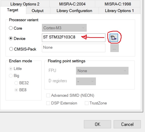
No hablaré sobre la instalación de IAR y controladores para el depurador. No hay nada nuevo aquí. Tengo IAR 8 con un límite de código de 32 kB. El controlador STM32F103 instalado en el tablero de pastillas plue se selecciona para su operación.
Ejecute IAR, cree un proyecto c ++, seleccione el controlador deseado,
el siguiente paso es estudiar la documentación. Nos interesará el manual de referencia RM0008. Lo principal es leer con atención.
En general, cuando les enseñé a mis trabajadores a programar controladores, les di la tarea: encender el LED (conectado a la pata del controlador), usar un depurador, editar registros y leer la documentación.
Módulo RCC. Tucking
Este módulo generalmente se olvida. Solo recuerdan cuando es imposible hacer parpadear el LED.
¡Recuerda! Para encender cualquier periférico, ¡debe aplicarle pulsos de reloj! No puedes prescindir de él.
Los puertos de E / S se encuentran en el bus APB2. Encontramos en la documentación un registro para controlar el reloj de este bus, este es RCC_APB2ENR:

Para habilitar el reloj del puerto C (el LED está soldado a PC13), debe escribir uno en el bit IOPCEN.
Ahora busquemos la dirección del registro RCC_APB2ENR. Su desplazamiento es 0x18, la dirección base para los registros RCC es 0x40021000.
Para que sea conveniente trabajar con bits, creemos una estructura:
typedef struct
{
  uint32_t  AFIOEN         : 1;
  uint32_t                 : 1;
  uint32_t  IOPAEN         : 1;
  uint32_t  IOPBEN         : 1;
  uint32_t  IOPCEN         : 1;
  uint32_t  IOPDEN         : 1;
  uint32_t  IOPEEN         : 1;
  uint32_t                 : 2;
  uint32_t  ADC1EN         : 1;
  uint32_t  ADC2EN         : 1;
  uint32_t  TIM1EN         : 1;
  uint32_t  SPI1EN         : 1;
  uint32_t                 : 1;
  uint32_t  USART1EN       : 1;
  uint32_t                 :17;
} RCC_APB2ENR_b;
Para no sufrir más tarde, listaremos inmediatamente todas las direcciones de registro:
enum AddrRCC
{
  RCC_CR          = 0x40021000,
  RCC_CFGR        = 0x40021004,
  RCC_CIR         = 0x40021008,
  RCC_APB2RSTR    = 0x4002100C,
  RCC_APB1RSTR    = 0x40021010,
  RCC_AHBENR      = 0x40021014,
  RCC_APB2ENR     = 0x40021018,
  RCC_APB1ENR     = 0x4002101C,
  RCC_BDCR        = 0x40021020,
  RCC_CSR         = 0x40021024
};
ahora queda escribir el código para habilitar los periféricos:
static void EnablePort(uint8_t port_name)
{
  volatile RCC_APB2ENR_b* apb2enr = reinterpret_cast<RCC_APB2ENR_b*>(RCC_APB2ENR);
  switch (port_name)
  {
    case 'A': apb2enr->IOPAEN = 1; break;
    case 'a': apb2enr->IOPAEN = 1; break;
    case 'B': apb2enr->IOPBEN = 1; break;
    case 'b': apb2enr->IOPBEN = 1; break;
    case 'C': apb2enr->IOPCEN = 1; break;
    case 'c': apb2enr->IOPCEN = 1; break;
    case 'D': apb2enr->IOPDEN = 1; break;
    case 'd': apb2enr->IOPDEN = 1; break;
    case 'E': apb2enr->IOPEEN = 1; break;
    case 'e': apb2enr->IOPEEN = 1; break;
  }
}
Cuando trabaje con registros, no se olvide de los volátiles ; de lo contrario, después de la optimización por parte del compilador, buscaremos errores durante mucho tiempo y regañaremos a los desarrolladores del compilador.
Hacemos lo mismo para habilitar la sincronización de otros periféricos.
Como resultado, obtuvimos la siguiente clase (no todo está listado):
STM32F1xx_RCC.h
#pragma once
#include "stdint.h"
namespace STM32F1xx
{
  class RCC
  {
  protected:
    enum AddrRCC
    {
      RCC_CR          = 0x40021000,
      RCC_CFGR        = 0x40021004,
      RCC_CIR         = 0x40021008,
      RCC_APB2RSTR    = 0x4002100C,
      RCC_APB1RSTR    = 0x40021010,
      RCC_AHBENR      = 0x40021014,
      RCC_APB2ENR     = 0x40021018,
      RCC_APB1ENR     = 0x4002101C,
      RCC_BDCR        = 0x40021020,
      RCC_CSR         = 0x40021024
    };

    typedef struct {
      uint32_t  HSION          : 1;
      uint32_t  HSIRDY         : 1;
      uint32_t                 : 1;
      uint32_t  HSI_TRIM       : 5;
      uint32_t  HSI_CAL        : 8;
      uint32_t  HSEON          : 1;
      uint32_t  HSERDY         : 1;
      uint32_t  HSEBYP         : 1;
      uint32_t  CSSON          : 1;
      uint32_t                 : 4;
      uint32_t  PLLON          : 1;
      uint32_t  PLLRDY         : 1;
      uint32_t                 : 6;
    } RCC_CR_b;

    typedef struct {
      uint32_t  SW             : 2;
      uint32_t  SWS            : 2;
      uint32_t  HPRE           : 4;
      uint32_t  PPRE1          : 3;
      uint32_t  PPRE2          : 3;
      uint32_t  ADC_PRE        : 2;
      uint32_t  PLLSRC         : 1;
      uint32_t  PLLXTPRE       : 1;
      uint32_t  PLLMUL         : 4;
      uint32_t  USBPRE         : 1;
      uint32_t                 : 1;
      uint32_t  MCO            : 3;
      uint32_t                 : 5;
    } RCC_CFGR_b;

    typedef struct
    {
      uint32_t  TIM2EN         : 1;
      uint32_t  TIM3EN         : 1;
      uint32_t  TIM4EN         : 1;
      uint32_t                 : 8;
      uint32_t  WWDGEN         : 1;
      uint32_t                 : 2;
      uint32_t  SPI2EN         : 1;
      uint32_t                 : 2;
      uint32_t  USART2EN       : 1;
      uint32_t  USART3EN       : 1;
      uint32_t                 : 2;
      uint32_t  I2C1EN         : 1;
      uint32_t  I2C2EN         : 1;
      uint32_t  USBEN          : 1;
      uint32_t                 : 1;
      uint32_t  CANEN          : 1;
      uint32_t                 : 1;
      uint32_t  BKPEN          : 1;
      uint32_t  PWREN          : 1;
      uint32_t                 : 3;
    } RCC_APB1ENR_b;

    typedef struct
    {
      uint32_t  AFIOEN         : 1;
      uint32_t                 : 1;
      uint32_t  IOPAEN         : 1;
      uint32_t  IOPBEN         : 1;
      uint32_t  IOPCEN         : 1;
      uint32_t  IOPDEN         : 1;
      uint32_t  IOPEEN         : 1;
      uint32_t                 : 2;
      uint32_t  ADC1EN         : 1;
      uint32_t  ADC2EN         : 1;
      uint32_t  TIM1EN         : 1;
      uint32_t  SPI1EN         : 1;
      uint32_t                 : 1;
      uint32_t  USART1EN       : 1;
      uint32_t                 :17;
    } RCC_APB2ENR_b;

    typedef struct {
      uint32_t  DMAEN          : 1;
      uint32_t                 : 1;
      uint32_t  SRAMEN         : 1;
      uint32_t                 : 1;
      uint32_t  FLITFEN        : 1;
      uint32_t                 : 1;
      uint32_t  CRCEN          : 1;
      uint32_t                 :25;
    } RCC_AHBENR_r;

  public:
    static void EnablePort(uint8_t port_name)
    {
      volatile RCC_APB2ENR_b* apb2enr = reinterpret_cast<RCC_APB2ENR_b*>(RCC_APB2ENR);
      switch (port_name)
      {
        case 'A': apb2enr->IOPAEN = 1; break;
        case 'a': apb2enr->IOPAEN = 1; break;
        case 'B': apb2enr->IOPBEN = 1; break;
        case 'b': apb2enr->IOPBEN = 1; break;
        case 'C': apb2enr->IOPCEN = 1; break;
        case 'c': apb2enr->IOPCEN = 1; break;
        case 'D': apb2enr->IOPDEN = 1; break;
        case 'd': apb2enr->IOPDEN = 1; break;
        case 'E': apb2enr->IOPEEN = 1; break;
        case 'e': apb2enr->IOPEEN = 1; break;
      }
    }

    static void DisablePort(char port_name)
    {
      volatile RCC_APB2ENR_b* apb2enr = reinterpret_cast<RCC_APB2ENR_b*>(RCC_APB2ENR);
      switch (port_name)
      {
        case 'A': apb2enr->IOPAEN = 0; break;
        case 'a': apb2enr->IOPAEN = 0; break;
        case 'B': apb2enr->IOPBEN = 0; break;
        case 'b': apb2enr->IOPBEN = 0; break;
        case 'C': apb2enr->IOPCEN = 0; break;
        case 'c': apb2enr->IOPCEN = 0; break;
        case 'D': apb2enr->IOPDEN = 0; break;
        case 'd': apb2enr->IOPDEN = 0; break;
        case 'E': apb2enr->IOPEEN = 0; break;
        case 'e': apb2enr->IOPEEN = 0; break;
      }
    }

    static void EnableAFIO()
    {
      volatile RCC_APB2ENR_b* apb2enr = reinterpret_cast<RCC_APB2ENR_b*>(RCC_APB2ENR);
      apb2enr->AFIOEN = 1;
    }

    static void DisableAFIO()
    {
      volatile RCC_APB2ENR_b* apb2enr = reinterpret_cast<RCC_APB2ENR_b*>(RCC_APB2ENR);
      apb2enr->AFIOEN = 0;
    }

    static void EnableI2C(int PortNumber)
    {
      switch (PortNumber)
      {
        case 1:
        {
          volatile RCC_APB1ENR_b* apb1enr = reinterpret_cast<RCC_APB1ENR_b*>(RCC_APB1ENR);
          apb1enr->I2C1EN = 1;
          break;
        }
        case 2:
        {
          volatile RCC_APB1ENR_b* apb1enr = reinterpret_cast<RCC_APB1ENR_b*>(RCC_APB1ENR);
          apb1enr->I2C2EN = 1;
          break;
        }

      }
    }

    static void EnableUART(int PortNumber)
    {
      switch (PortNumber)
      {
        case 1:
        {
          volatile RCC_APB2ENR_b* apb2enr = reinterpret_cast<RCC_APB2ENR_b*>(RCC_APB2ENR);
          apb2enr->USART1EN = 1;
          break;
        }
        case 2:
        {
          volatile RCC_APB1ENR_b* apb1enr = reinterpret_cast<RCC_APB1ENR_b*>(RCC_APB1ENR);
          apb1enr->USART2EN = 1;
          break;
        }
        case 3:
        {
          volatile RCC_APB1ENR_b* apb1enr = reinterpret_cast<RCC_APB1ENR_b*>(RCC_APB1ENR);
          apb1enr->USART3EN = 1;
          break;
        }

      }
    }

    static void DisableUART(int PortNumber)
    {
      switch (PortNumber)
      {
        case 1:
        {
          volatile RCC_APB2ENR_b* apb2enr = reinterpret_cast<RCC_APB2ENR_b*>(RCC_APB2ENR);
          apb2enr->USART1EN = 0;
          break;
        }
        case 2:
        {
          volatile RCC_APB1ENR_b* apb1enr = reinterpret_cast<RCC_APB1ENR_b*>(RCC_APB1ENR);
          apb1enr->USART2EN = 0;
          break;
        }
        case 3:
        {
          volatile RCC_APB1ENR_b* apb1enr = reinterpret_cast<RCC_APB1ENR_b*>(RCC_APB1ENR);
          apb1enr->USART3EN = 0;
          break;
        }
      }
    }

    static void EnableSPI(int PortNumber)
    {
      switch (PortNumber)
      {
        case 1:
        {
          volatile RCC_APB2ENR_b* apb2enr = reinterpret_cast<RCC_APB2ENR_b*>(RCC_APB2ENR);
          apb2enr->SPI1EN = 1;
          break;
        }
        case 2:
        {
          volatile RCC_APB1ENR_b* apb1enr = reinterpret_cast<RCC_APB1ENR_b*>(RCC_APB1ENR);
          apb1enr->SPI2EN = 1;
          break;
        }
      }
    }

    static void DisableSPI(int PortNumber)
    {
      switch (PortNumber)
      {
        case 1:
        {
          volatile RCC_APB2ENR_b* apb2enr = reinterpret_cast<RCC_APB2ENR_b*>(RCC_APB2ENR);
          apb2enr->SPI1EN = 0;
          break;
        }
        case 2:
        {
          volatile RCC_APB1ENR_b* apb1enr = reinterpret_cast<RCC_APB1ENR_b*>(RCC_APB1ENR);
          apb1enr->SPI2EN = 0;
          break;
        }
      }
    }

    static void EnableDMA()
    {
      volatile RCC_AHBENR_r* ahbenr = reinterpret_cast<RCC_AHBENR_r*>(RCC_AHBENR);
      ahbenr->DMAEN = 1;
    }

    static void DisableDMA()
    {
      volatile RCC_AHBENR_r* ahbenr = reinterpret_cast<RCC_AHBENR_r*>(RCC_AHBENR);
      ahbenr->DMAEN = 0;
    }
  };
}
Ahora puede adjuntar un archivo en main.cpp y usar:
#include "STM32F1xx_RCC.h"

using namespace STM32F1xx;

int main()
{
  RCC::EnablePort('c');
  return 0;
}
Ahora puedes trabajar con los puertos. GPIO
Abra la sección E / S de uso general y función alternativa en la documentación. Busque la tabla de configuración de bits del puerto:

Los bits CNF [1: 0] establecen el modo de operación del puerto (entrada analógica, entrada digital, salida), los bits MODE [1: 0] corresponden a la velocidad de operación del puerto en el modo de salida.
Echemos un vistazo a los registros GPIOx_CRL y GPIOx_CRH (x = A, B, C, ...),

puede ver que los bits van secuencialmente:
CNF [1: 0], MODE [1: 0]
luego crearemos constantes con los modos de puerto
enum mode_e
{
  ANALOGINPUT             = 0,
  INPUT                   = 4,
  INPUTPULLED             = 8,

  OUTPUT_10MHZ            = 1,
  OUTPUT_OD_10MHZ         = 5,
  ALT_OUTPUT_10MHZ        = 9,
  ALT_OUTPUT_OD_10MHZ     = 13,

  OUTPUT_50MHZ            = 3,
  OUTPUT_OD_50MHZ         = 7,
  ALT_OUTPUT_50MHZ        = 11,
  ALT_OUTPUT_OD_50MHZ     = 15,

  OUTPUT_2MHZ             = 2,
  OUTPUT_OD_2MHZ          = 6,
  ALT_OUTPUT_2MHZ         = 10,
  ALT_OUTPUT_OD_2MHZ      = 14,

  OUTPUT                  = 3,
  OUTPUT_OD               = 7,
  ALT_OUTPUT              = 11,
  ALT_OUTPUT_OD           = 15
};
entonces el método de configuración se verá así:
// pin_number -
void Mode(mode_e mode)
{
  uint32_t* addr;
  if(pin_number > 7)
    addr = reinterpret_cast<uint32_t*>(GPIOA_CRH);
  else
    addr = reinterpret_cast<uint32_t*>(GPIOA_CRL);

  int bit_offset;
  if(pin_number > 7)
    bit_offset = (pin_number - 8) * 4;
  else
    bit_offset = pin_number * 4;

  uint32_t mask = ~(15 << bit_offset);
  *addr &= mask;
  *addr |= ((int)mode) << bit_offset;
}
ahora podemos crear métodos más convenientes para seleccionar un modo:
    void ModeInput()              { Mode(INPUT);         }
    void ModeAnalogInput()        { Mode(ANALOGINPUT);   }
    void ModeInputPulled()        { Mode(INPUTPULLED);   }
    void ModeOutput()             { Mode(OUTPUT);        }
    void ModeOutputOpenDrain()    { Mode(OUTPUT_OD);     }
    void ModeAlternate()          { Mode(ALT_OUTPUT);    }
    void ModeAlternateOpenDrain() { Mode(ALT_OUTPUT_OD); }
En la documentación, encontramos las direcciones de los registros de control para los puertos y los listamos:
enum AddrGPIO
{
  PortA           = 0x40010800,
  GPIOA_CRL       = 0x40010800,
  GPIOA_CRH       = 0x40010804,
  GPIOA_IDR       = 0x40010808,
  GPIOA_ODR       = 0x4001080C,
  GPIOA_BSRR      = 0x40010810,
  GPIOA_BRR       = 0x40010814,
  GPIOA_LCKR      = 0x40010818,
  PortB           = 0x40010C00,
  PortC           = 0x40011000,
  PortD           = 0x40011400,
  PortE           = 0x40011800,
  PortF           = 0x40011C00,
  PortG           = 0x40012000
};
Durante mucho tiempo se pensó en utilizar la dirección base y las compensaciones o direcciones absolutas. Al final, me detuve en este último. Esto agrega algo de sobrecarga, pero es más fácil de encontrar en la memoria durante la depuración.
Modernicemos el método:
if(pin_number > 7)
  addr = reinterpret_cast<uint32_t*>(GPIOA_CRH - PortA + PortAddr);
else
  addr = reinterpret_cast<uint32_t*>(GPIOA_CRL - PortA + PortAddr);
Quizás alguien tenga un tic en el ojo, pero todavía no he encontrado uno más hermoso.
Para transferir el tramo al estado lógico deseado, basta con escribir el bit correspondiente en el registro ODRx. Por ejemplo, así:
void Set(bool st)
{
  uint32_t* addr;
  addr = reinterpret_cast<uint32_t*>(GPIOA_ODR - PortA + PortAddr);

  if(st)
    *addr |= 1 << pin_number;
  else
  {
    int mask = ~(1 << pin_number);
    *addr &= mask;
  }
}
También puede utilizar los registros GPIOx_BSRR para controlar el estado.
Por analogía, creamos métodos para leer el estado del puerto, métodos de configuración e inicialización (no olvide habilitar el reloj). Como resultado, obtuvimos la siguiente clase para trabajar con puertos:
STM32F1xx_Pin.h
#pragma once
#include <stdint.h>
#include "STM32F1xx_RCC.h"

namespace STM32F1xx
{
  class Pin
  {
  public:
    enum mode_e
    {
      ANALOGINPUT             = 0,
      INPUT                   = 4,
      INPUTPULLED             = 8,

      OUTPUT_10MHZ            = 1,
      OUTPUT_OD_10MHZ         = 5,
      ALT_OUTPUT_10MHZ        = 9,
      ALT_OUTPUT_OD_10MHZ     = 13,

      OUTPUT_50MHZ            = 3,
      OUTPUT_OD_50MHZ         = 7,
      ALT_OUTPUT_50MHZ        = 11,
      ALT_OUTPUT_OD_50MHZ     = 15,

      OUTPUT_2MHZ             = 2,
      OUTPUT_OD_2MHZ          = 6,
      ALT_OUTPUT_2MHZ         = 10,
      ALT_OUTPUT_OD_2MHZ      = 14,

      OUTPUT                  = 3,
      OUTPUT_OD               = 7,
      ALT_OUTPUT              = 11,
      ALT_OUTPUT_OD           = 15
    };

  private:
    enum AddrGPIO
    {
      PortA           = 0x40010800,
      GPIOA_CRL       = 0x40010800,
      GPIOA_CRH       = 0x40010804,
      GPIOA_IDR       = 0x40010808,
      GPIOA_ODR       = 0x4001080C,
      GPIOA_BSRR      = 0x40010810,
      GPIOA_BRR       = 0x40010814,
      GPIOA_LCKR      = 0x40010818,
      PortB           = 0x40010C00,
      PortC           = 0x40011000,
      PortD           = 0x40011400,
      PortE           = 0x40011800,
      PortF           = 0x40011C00,
      PortG           = 0x40012000
    };

  private:
    int   pin_number;
    int   PortAddr;

  public:
    Pin()                               { }
    Pin(char port_name, int pin_number) { Init(port_name, pin_number); }
    ~Pin()
    {
      Off();
      ModeAnalogInput();
    }
  public:
    void Init(char port_name, int pin_number)
    {
      this->pin_number = pin_number;
      RCC::EnablePort(port_name);
      switch (port_name)
      {
        case 'A': PortAddr = PortA; break;
        case 'a': PortAddr = PortA; break;
        case 'B': PortAddr = PortB; break;
        case 'b': PortAddr = PortB; break;
        case 'C': PortAddr = PortC; break;
        case 'c': PortAddr = PortC; break;
        case 'D': PortAddr = PortD; break;
        case 'd': PortAddr = PortD; break;
        case 'E': PortAddr = PortE; break;
        case 'e': PortAddr = PortE; break;
      }
    }

    void ModeInput()              { Mode(INPUT);         }
    void ModeAnalogInput()        { Mode(ANALOGINPUT);   }
    void ModeInputPulled()        { Mode(INPUTPULLED);   }
    void ModeOutput()             { Mode(OUTPUT);        }
    void ModeOutputOpenDrain()    { Mode(OUTPUT_OD);     }
    void ModeAlternate()          { Mode(ALT_OUTPUT);    }
    void ModeAlternateOpenDrain() { Mode(ALT_OUTPUT_OD); }

    void NoPullUpDown()
    {
      uint32_t* addr;
      if(pin_number > 7)
        addr = reinterpret_cast<uint32_t*>(GPIOA_CRH - PortA + PortAddr);
      else
        addr = reinterpret_cast<uint32_t*>(GPIOA_CRL - PortA + PortAddr);

      int bit_offset;
      if(pin_number > 7)
        bit_offset = (pin_number - 8) * 4;
      else
         bit_offset = pin_number * 4;

      int mask = ~((1 << 3) << bit_offset);
      *addr &= mask;
    }

    void Mode(mode_e mode)
    {
      uint32_t* addr;
      if(pin_number > 7)
        addr = reinterpret_cast<uint32_t*>(GPIOA_CRH - PortA + PortAddr);
      else
        addr = reinterpret_cast<uint32_t*>(GPIOA_CRL - PortA + PortAddr);

      int bit_offset;
      if(pin_number > 7)
        bit_offset = (pin_number - 8) * 4;
      else
        bit_offset = pin_number * 4;

      uint32_t mask = ~(15 << bit_offset);
      *addr &= mask;
      *addr |= ((int)mode) << bit_offset;
    }

    void Set(bool st)
    {
      uint32_t* addr;
      addr = reinterpret_cast<uint32_t*>(GPIOA_ODR - PortA + PortAddr);

      if(st)
        *addr |= 1 << pin_number;
      else
      {
        int mask = ~(1 << pin_number);
        *addr &= mask;
      }
    }

    void On()
    {
      uint32_t* addr;
      addr = reinterpret_cast<uint32_t*>(GPIOA_ODR - PortA + PortAddr);
      int bit_offset = pin_number;
      *addr |= 1 << bit_offset;
    }

    void Off()
    {
      uint32_t* addr;
      addr = reinterpret_cast<uint32_t*>(GPIOA_ODR - PortA + PortAddr);
      int bit_offset = pin_number;
      int mask = ~(1 << bit_offset);
      *addr &= mask;
    }

    bool Get()
    {
      uint32_t* addr = reinterpret_cast<uint32_t*>(GPIOA_IDR - PortA + PortAddr);
      int bit_offset = pin_number;
      int mask = (1 << bit_offset);
      bool ret_val = (*addr & mask);
      return ret_val;
    }
  };
};
Bueno, intentemos:
#include "STM32F1xx_Pin.h"

using namespace STM32F1xx;

Pin led('c', 13);

int main()
{
  led.ModeOutput();
  led.On();
  led.Off();
  return 0;
}
Pasamos por el depurador y nos aseguramos de que el LED se enciende primero (después de led.ModeOutput ();), luego se apaga (led.On ();) y se vuelve a encender (led.Off ();). Esto se debe a que el LED está conectado a la pierna a través de la línea eléctrica. Por lo tanto, cuando el pin está bajo, el LED se enciende.
No grandes totales
En este artículo he intentado (espero que haya tenido éxito) mostrar cómo puedes simplificar un poco tu vida, hacer que el código sea más legible. O viceversa, cómo no hacerlo. Todos decidirán por sí mismos.
Era posible escribir simplemente envoltorios para CMSIS, pero esto no es interesante.
Gracias por tu tiempo. Si está interesado en la secuela, hágamelo saber.